Attiny25/45/85 PWM.
At a silly 500KHz and still 8-bit resolution.
To unlock the full potential and power of such a "tiny" microcontroller this tutorial will be as bare bones as possible.
Requisites:
- WinAVR installed on Windows.
- WinAVR added to the PATH (makes life easier in the command line)
- OR the Arduino IDE installed (we'll just borrow some files from it)
- a programmer like: https://tinyurl.com/y2odglry
If you only have the Arduino IDE that's fine, actually better because it already has core files we'll need that already describes ALL the registers for us. The default install on windows
C:\Program Files (x86)\Arduino\hardware\tools\avr
has everything needed already to work with just about any Atmel device from an attiny to the SAMD's. There's linkers, compilers, and flashers, which you can also use to set fuse bits. For this quick tutorial, we'll just need a few files copied to a directory of your choice (I made one right on the C drive: C:\attiny ).
- io.h
- iotn85.h
- iotnx5.h
Alternatively, you can grab the needed files from my GitHub.
Open ANY text editor (Geany and Notepad++ are free and great, also have themes/syntax highlighting), save the new file as tinypwm.c .
A snippet and very basic program to setup Timer 1 on an attiny25/45/85
without and with deadtime control.
*/
#include <C:\attiny\io.h>
int main(){
//setup
PLLCSR = 0x6; //enable PLL clock for PWM high frequency clock to TCNT1
DDRB = 0x3; //output PB0 & PB1 (OC0A / OC1A)
TCCR1 = 0x51; //PWM1A on, OC1A cleared / !OC1A set, clock select 1:1
OCR1A = 8; //PWM 127 ~50%
OCR1C = 255; //PWM freq (clears TCNT1 on match, affects resolution) //~250KHz when OCR1C = 0xff
DTPS1 = 0; //dead time prescaler 2-bit
//DT1A = 0x33; //dead time H[7..4] & L[3..0]
//loop
while(1){}
}
PLLCSR = 0x06 enables the PLL ClocK (PCK) for the system OR Timer1, since stock settings of the lfuse has the internal 8MHz RC clock selected and CDIV/8 for the cpu resulting in 1MHz cpu clock and 64MHz PLL clock for Timer1
Timer 1 control register (TCCR1) bits set so PWM1A selected (OC0A / OC1A = PB0 / PB1), action on compare is to toggle and clock prescale is 1:1
OCR1A = (total dead time + 1)..(OCR1C-1) this represents the duty % of OCR1C. (for PWM to actually toggle, this needs to be less than OCR1C, but more than the total dead time.
OCR1C = 2..255 this register clears TCNT1 on compare, which OCR1A uses to toggle PBO / PB1. This is why OCR1A MUST be less than OCR1C for PWM to work.
DTPS1 = 0..3 the CK or PCK prescaler for the deadtimes between complimentary outputs <0 = 1:1, 3 = 1:8 deatime clock : CK or PCK> DT1A = 0x33; dead time H[7..4] & L[3..0] here I arbitrarily set to 4 clocks separation of OC1A cleared / !OC1A set. This is useful for controlling high power switching transistors in a syncronised SMPS power supply or H-Bridge. Ideally you adjust the deatimes according to the turn-on/off times of your transistors and drivers so when the complimentary outputs switch, the duty number is lessened by the total dead time.

Next, type: avr-gcc and hit enter, you should have an output like this: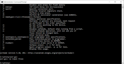 With the terminal looking like this your all ready to go for compiling and flashing. If not you likely don't have one or both configured in your PATH (plenty of information out there on how to do that).
 Your window should look like this if all went well. You should now have a new file in your folder called a.out. If it complains about things not being defined, you don't have the include typed correctly or the keywords are not correct or all caps.
Now its time to flash the attiny with your instructions, with the attiny installed in the programmer and the programmer recognized by windows your ready. Type:
avrdude -p t85 -c usbtiny -U flash:w:a.hex:i and hit enter. This should be the output:

while(1){}
}
PLLCSR = 0x06 enables the PLL ClocK (PCK) for the system OR Timer1, since stock settings of the lfuse has the internal 8MHz RC clock selected and CDIV/8 for the cpu resulting in 1MHz cpu clock and 64MHz PLL clock for Timer1
Timer 1 control register (TCCR1) bits set so PWM1A selected (OC0A / OC1A = PB0 / PB1), action on compare is to toggle and clock prescale is 1:1
OCR1A = (total dead time + 1)..(OCR1C-1) this represents the duty % of OCR1C. (for PWM to actually toggle, this needs to be less than OCR1C, but more than the total dead time.
OCR1C = 2..255 this register clears TCNT1 on compare, which OCR1A uses to toggle PBO / PB1. This is why OCR1A MUST be less than OCR1C for PWM to work.
DTPS1 = 0..3 the CK or PCK prescaler for the deadtimes between complimentary outputs <0 = 1:1, 3 = 1:8 deatime clock : CK or PCK> DT1A = 0x33; dead time H[7..4] & L[3..0] here I arbitrarily set to 4 clocks separation of OC1A cleared / !OC1A set. This is useful for controlling high power switching transistors in a syncronised SMPS power supply or H-Bridge. Ideally you adjust the deatimes according to the turn-on/off times of your transistors and drivers so when the complimentary outputs switch, the duty number is lessened by the total dead time.
Save the file with the .c extension in your attiny directory.
Hit the windows key and type: cmd . A search will pop up over the windows menu, click "Run as Administrator". You now have the command line in front of you and your location is the default for windows.

You'll need to change directories to your attiny directory. Type: cd C:\attiny and hit enter, then dir and enter.
you should now see the files you'll need to work with the attiny easily:
- io.h
- iotn85.h
- iotnx5.h
- tinypwm.c

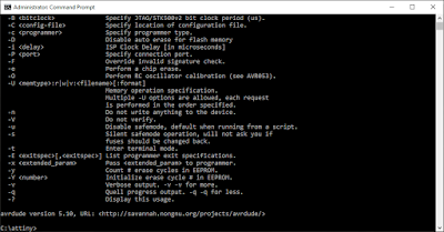
I have WinAVR installed and configured for windows PATH. To check if your PATH is configured properly, type: avrdude and hit enter. If all is well you'll see this:

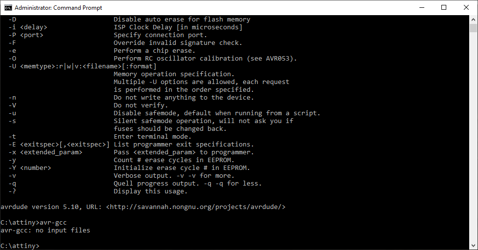
Next, type: avr-gcc and hit enter, you should have an output like this:
Setup & ready to GO!
So now lets compile that bit of code you wrote for the Attiny85, in the command line type: avr-gcc -Os -mmcu=attiny85 tinypwm.c and hit enter. If there were no errors it returns silently to the command line.

Next, run the avr-objcopy to translate to intel hex file the flasher and mcu will understand. Type: avr-objcopy -O ihex -j .text -j .data a.out a.hex , hit enter and if all is well it will also return silently.

Now its time to flash the attiny with your instructions, with the attiny installed in the programmer and the programmer recognized by windows your ready. Type:
avrdude -p t85 -c usbtiny -U flash:w:a.hex:i and hit enter. This should be the output:

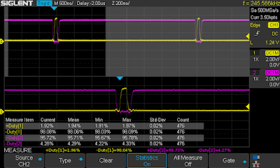
As you can see, setting up the PWM to output a steady signal at 250KHz with OCR1A = 8 gives a 3% duty cycle on PB1 (OC1A) and 96% duty on PB0 (!OC1A).

Going back to edit the tinypwm.c file in the text editor and uncommenting (removing the //) from in front of the line DT1A tells the attiny to enable the dead time generator within the Timer 1. In binary (which is what the registers are setup as), DT1A = 0x33 = binary H0011 L0011. This means that the dead time between OC1A turning ON and !OC1A turning OFF. Up to 32 clocks can be setup between DTPS1 - the dead time clock prescasler <0..3> and DT1A registers.
With dead time configured you can see the difference between the O-scope shots.

The observant will notice that the duty for channel 1 (yellow) reduced by about 1% because of the dead time being generated. In a configuration where you have to synchronize two mosfets connected in series across the power supply like in an H-Bridge, its undesirable to switch the high side and low side mosfet at the same time because of the combined rise and fall times of the mosfet drivers and the mosfets. If the drivers are switched at the same time (no dead time), as mosfet A is switched off and mosfet B is switched on there will be a small amount of time when BOTH mosfets are at least partially on effectively shorting the power supply and causing power to be dissipated in the mosfets as heat. It also has the effect of making your SMPS or H-bridge design less efficient, so dead time is desirable and is the minimum time for your transistors to switch correctly and efficiently.
More frequency? Yes please.
Changing OCR1C to 127 from 255 has the effect of doubling the PWM frequency to ~500KHz but halving the resolution to 126 steps from 254. Likewise if you set OCR1C to 63, the frequency will be over 1MHz but resolution drops to 62 levels. Dead time settings will also have an effect the minimum and maximum duty cycle for a given frequency. The switching times of your mosfets and gate drivers will dictate the maximum frequency and/or resolution you'll be able to program.